Magnetic drive pump

Blog

Home

Blog

  • What is Centrifugal Pump? Parts, Working Principle and Types What is Centrifugal Pump? Parts, Working Principle and Types
    Aug 04, 2025
    Introduction A centrifugal pump is a mechanical device that converts the rotational energy of an impeller into fluid kinetic energy to transport liquids. Centrifugal pumps are widely used in industries such as water treatment, oil and gas, chemical processing, and HVAC systems, and are key equipment for efficient liquid transportation. In this article, we will explore the working principle of centrifugal pumps, their key components, different types, and applications to help you gain a comprehensive understanding of what centrifugal pumps are. Continue reading to learn more! How Does a Centrifugal Pump Work?   The working principle of a centrifugal pump involves an electric motor driving the impeller to rotate at high speed, thereby causing the liquid inside the pump to form a rotating flow and generating high kinetic energy at the impeller outlet. Under the influence of centrifugal force, the liquid flows along the pump casing toward the outlet or is transported to the next stage impeller. Simultaneously, a low-pressure zone forms at the center of the impeller due to the outflow of liquid, creating a pressure difference with the liquid at the suction inlet, which drives the liquid to continuously enter the pump body. As the impeller continues to rotate, the pump achieves continuous suction and discharge, completing the liquid transportation process.     Centrifugal Pumps Parts The centrifugal pump parts mainly consist of impellers, pump casings, pump shafts, bearing assemblies, sealing devices, suction and discharge ports, and drive motors. The following are the functional characteristics of each component:   Impeller: The impeller is the rotating element that imparts kinetic energy to the fluid, generating centrifugal force to move the liquid outward. Pump Casing: The casing encloses the impeller and directs the flow of liquid from the impeller to the discharge outlet while converting velocity into pressure. Shaft: The shaft transmits mechanical energy from the motor to the impeller, maintaining stable rotation and alignment. Bearing Assembly: Bearings support the shaft and reduce friction, making is smooth and precise operation. Mechanical Seal or Packing: Prevent liquid from leaking along the shaft where it exits the casing. Suction and Discharge Nozzles: The suction nozzle allows fluid to enter the pump, while the discharge nozzle guides it out under pressure. Motor or Driver: The motor provides the necessary power to rotate the impeller and drive the pumping process.   Types of Centrifugal Pumps industrial centrifugal pumps have a variety of designs and models to meet different industrial application needs. The following are some common types: Centrifugal Pump​ Magnetic Pump Self-Priming Pump Submersible Pump   Magnetic Drive Pumps: Utilize leak-free magnetic drive technology, suitable for transporting flammable, explosive, or toxic media (such as solvents, liquid chlorine). Semi-Submersible Pumps: The motor is exposed above the liquid surface, suitable for applications with significant fluctuations in water level (such as drainage stations, temporary flood control). Self-priming pumps: Equipped with an air release function, eliminating the need for manual priming, suitable for intermittent suction (e.g., ship ballasting, construction site drainage). Diaphragm pumps: Utilize diaphragm reciprocating motion to transport high-viscosity or particulate-containing liquids (e.g., slurry, paint). Water pumps: General-purpose design for clean water transportation (e.g., municipal water supply, agricultural irrigation). Acid pumps: Manufactured using corrosion-resistant materials (e.g., PVDF, Hastelloy), specifically designed for acidic media (e.g., sulfuric acid, hydrochloric acid). Alkali pumps: Equipped with special seals and material processing techniques, suitable for strong alkaline liquids (e.g., sodium hydroxide, electrolyte).   What is centrifugal pump used for?   Industrial centrifugal pumps are widely used across multiple industries: Water & Wastewater: Transferring clean water, sewage, and stormwater in treatment plants. Oil & Gas: Transporting crude oil, refinery fluids, and seawater in offshore operations. Chemical & Pharma: Handling corrosive acids, solvents, and sterile pharmaceutical liquids. Power Plants: Circulating boiler feedwater, cooling water, and condensate in energy generation. Mining & Manufacturing: Pumping abrasive slurries and industrial coolants. Agriculture: Distributing irrigation water and agrochemicals efficiently. Advantages of Centrifugal Pumps   High Efficiency: Engineered for optimal energy conversion, delivering superior flow rates with minimal power consumption. Low Maintenance: Simplified mechanical design with only one rotating component (impeller) reduces wear and maintence. Compact Footprint: Space-saving vertical/horizontal configurations adapt to constrained industrial layouts. Material Versatility: Available in stainless steel, cast iron, fluoroplastic and advanced polymers to handle corrosive/abrasive media. Pulsation-Free Operation: Continuous rotary motion ensures smooth, vibration-free fluid transfer critical for precision processes.   Conclusion Centrifugal pumps are versatile, highly efficient, and widely used, making them the core equipment of modern fluid delivery systems. As a professional pump solution provider, we focus on meeting the special fluid handling needs of various industries and offer comprehensive customized services. If you need the most suitable pumping solution for your working conditions, please feel free to contact our technical experts for consultation.  
    Read More
  • Understand The Centrifugal Pump Parts And Working Understand The Centrifugal Pump Parts And Working
    Aug 21, 2025
    A centrifugal pump is a type of pump that utilizes the principle of centrifugal force to transport liquids. Its core function is to convert the rotational kinetic energy of an electric motor or engine into fluid energy, thereby generating flow and pressure. In this article, we will take an in-depth look at the key components of a centrifugal pump and its working principles. We will break down each component and explain its operational process to help you gain a clear and comprehensive understanding of this equipment.     Centrifugal Pump Parts Although there are many types of centrifugal pumps with different applications, their basic core structures are similar. Understanding these key components will help you understand how centrifugal pumps work. We will provide a detailed introduction to the main core components of centrifugal pumps, including impellers, pump casings, and sealing systems. Impeller It is one of the core components of a centrifugal pump, primarily responsible for transferring mechanical energy from the motor to the liquid, generating centrifugal force to impart kinetic and potential energy to the liquid. Types of impellers: Based on structural form, they are divided into open, semi-open, and closed types. Closed impellers have the highest efficiency and are the most widely used; open and semi-open impellers are suitable for conveying fluids containing solid particles or viscous fluids. When the centrifugal pump starts, the pump shaft drives the impeller to rotate at high speed, forcing the liquid pre-filled between the blades to rotate. Under the influence of inertial centrifugal force, the liquid moves radially from the center to the outer periphery of the impeller. The liquid gains energy as it flows through the impeller. When the liquid leaves the impeller and enters the pump casing, it decelerates due to the gradually expanding flow channels inside the casing, converting part of its kinetic energy into static pressure energy, and finally flows tangentially into the discharge pipeline.     Pump casing:   The pump casing refers to the spiral-shaped flow channel with gradually increasing cross-sectional area from the impeller outlet to the inlet of the next stage impeller or to the pump outlet pipe. The flow channel gradually widens, converting the fluid's kinetic energy into static pressure energy, which is then discharged through the pipe. Main functions:   Collecting high-speed fluid flowing out from the impeller outlet;   Effectively converting the fluid's kinetic energy into pressure energy;   Smoothly guiding the pressurized fluid to the pump's discharge piping;   Withstanding the fluid pressure inside the pump.     Types:   Snail-shell type pump casing: The most common type, with a spiral-shaped flow channel cross-section and a simple structure. Guide vane pump casing: Features fixed guide vanes mounted around the impeller's periphery. The guide vanes convert the fluid's kinetic energy into pressure energy and direct the fluid toward the outlet. Commonly used in multistage pumps or high-pressure pumps.   Pump shaft Its primary function is to transmit power and support the impeller to maintain normal operation at its working position. Since it must perform additional energy conversion functions, its material must possess sufficient strength, stiffness, and wear resistance. It is typically made of high-strength alloy steel. The impeller and shaft are connected via a key. Since this connection method can only transmit torque and cannot fix the axial position of the impeller, a shaft sleeve and locking nut are also used in the pump to secure the axial position of the impeller.   Shaft sleeve The shaft sleeve protects the pump shaft, transforming the friction between the packing and the shaft into friction between the packing and the shaft sleeve. Therefore, the shaft sleeve is a wear-prone component in centrifugal pumps. The surface of the shaft sleeve can typically be treated using methods such as carburizing, nitriding, chrome plating, or coating. The surface roughness requirement generally needs to reach Ra3.2 μm to Ra0.8 μm. This reduces the friction coefficient and extends the service life.   Skeleton oil seal A skeleton oil seal is one of the most common and widely used types of seals for rotating shafts, commonly known as oil seals. Its primary function is to seal lubricating oil (or grease) within mechanical equipment while preventing external contaminants such as dust and mud from entering the system. Centrifugal Pump Working Principle The working principle of centrifugal pump involves the high-speed rotation of the impeller, which imparts kinetic energy to the liquid under the influence of centrifugal force and converts it into pressure energy, thereby achieving fluid conveyance. Before startup, the pump housing and suction piping must be completely filled with the medium to prevent cavitation. During operation, the rotating impeller causes the liquid to move at high speed and be flung toward the outer edge, while a low-pressure zone forms at the center of the impeller, continuously drawing in liquid and conveying it to the outlet. Through continuous cyclic operation, a steady and continuous conveying process is achieved.   Conclusion Through the above content, we believe you now have a good understanding of centrifugal pump parts and how they work. If you have any further questions or technical issues regarding this equipment, please feel free to contact the Changyu technical team at any time. We will respond quickly within 24 hours and address your concerns.
    Read More
  • What Is The Difference Between Magnetic Drive Pump Vs Centrifugal Pump What Is The Difference Between Magnetic Drive Pump Vs Centrifugal Pump
    Sep 05, 2025
    Both magnetic drive pumps and centrifugal pumps belong to the category of centrifugal pumps, widely used in industrial fluid transfer applications. They both utilize centrifugal force to increase fluid kinetic energy and pressure, yet they exhibit numerous differences. This article provides an in-depth analysis of the differences between magnetic drive pumps vs centrifugal pumps. We'll comprehensively compare their working principles, structure, application areas, advantages, and disadvantages. This will help you clearly understand how to make the most informed choice based on your medium characteristics, safety requirements, and budget. Please continue reading to find the pumping solution best suited to your project needs. I. Working Principle Magnetic Drive Pump: Magnetic drive pumps utilize magnetic coupling principles to transmit power. When the motor operates, it drives the outer magnetic rotor to rotate at high speed. Through the magnetic field interaction, the inner magnetic rotor within the isolation sleeve rotates synchronously, thereby driving the impeller to perform centrifugal motion. Its enclosed transmission structure fundamentally eliminates leakage risks. Although magnetic drive pumps employ a different transmission method, they still belong to the category of centrifugal pumps, all relying on the centrifugal force generated by impeller rotation to convey fluids.   Centrifugal Pump: As the most prevalent fluid transfer equipment, centrifugal pumps operate based on the centrifugal effect generated by impeller rotation. When the motor drives the pump shaft to rotate the impeller at high speed, the fluid is flung from the impeller's center toward its periphery under centrifugal force. During this process, the fluid's kinetic and pressure energy continuously increase, ultimately forming a stable flow stream discharged through the outlet. This highly efficient energy conversion method makes it the most widely used pump type in industrial applications.   II. Structure Magnetic drive pump: Magnetic pump mainly consists of two parts: the driving part (including the motor and the external magnet) and the transmission part (including the internal magnet and the impeller). The power transmission is achieved through magnetic coupling between the two parts, without the need for a traditional shaft seal structure, good sealing and leak-free.   Centrifugal pump: Centrifugal pumps are usually composed of impellers, pump bodies, pump shafts, bearings, sealing rings and other parts. Among them, as an important component to block fluid leakage, the seal may fail due to wear or media corrosion during long-term operation, causing leakage problems.   III. Applications Magnetic Drive Pumps: Featuring a shaftless design that completely eliminates leakage risks, magnetic drive pumps offer excellent corrosion resistance. They are particularly suitable for conveying flammable, explosive, toxic, or highly corrosive media. These pumps are widely used in high-risk and high-purity processes such as petroleum refining, fine chemicals, biopharmaceuticals, surface treatment, and environmental engineering.   Centrifugal Pumps: Centrifugal pumps feature robust mechanical construction, stable operational performance, and excellent adaptability to varying conditions, making them one of the most widely used fluid transfer devices. They are extensively applied in industrial processes, agricultural irrigation, municipal water supply and drainage, building fire protection, and HVAC systems.  
    Read More
  • Horizontal vs Vertical Centrifugal Pumps and How to Choose Horizontal vs Vertical Centrifugal Pumps and How to Choose
    Sep 01, 2025
    In industrial fluid transfer systems, horizontal centrifugal pumps and vertical centrifugal pumps are the two most common pump types. Simply put, horizontal centrifugal pumps feature a horizontally mounted shaft, a simple structure, and are widely used in water supply, air conditioning circulation, and industrial pressurization applications. Vertical centrifugal pumps, with their vertically oriented shafts, are commonly used for pumping from low-level liquid reservoirs (such as underground tanks or drainage pits) or in applications with limited installation space. Although both belong to the centrifugal pump category and share similar hydraulic performance, they exhibit significant differences in structure, installation, maintenance, and application scenarios. Below, we provide a detailed comparison across multiple dimensions to help you make a more suitable choice.   Structural Comparison Horizontal centrifugal pumps feature a horizontally arranged shaft, with the motor typically directly coupled to the pump body via a coupling. This compact design facilitates installation and commissioning. Visually, their base is usually monolithic and requires anchoring to a foundation platform.   Vertical centrifugal pumps employ a vertical shaft design, with the motor positioned above the pump body, allowing the pump to operate submerged in liquid. Their slender structure generally eliminates the need for additional foundation supports, allowing direct installation atop tanks or reservoirs to save floor space.   Working Principle Despite differing installation methods, both share identical core operating principles. Both horizontal and vertical centrifugal pumps rely on the centrifugal force generated by a high-speed rotating impeller to expel fluid, creating a vacuum that draws in liquid for continuous conveyance.   Advantages and Application Scenarios Comparison   Horizontal Centrifugal Pump Advantages and Applications   Advantages:   Easy Maintenance: Simple structure requires no pipeline disassembly or motor lifting during repairs, facilitating inspection and component replacement. Stable Operation: Typically suited for steady-state conditions. Installation must ensure level positioning, resulting in low vibration and reliable operation. Applications: Horizontal centrifugal pumps are the preferred choice for most conventional applications, commonly used in factory water supply, cooling systems, industrial cleaning, and similar scenarios.   Advantages and Applications of Vertical Centrifugal Pumps   Advantages:   Suitable for Backflow Conditions: Particularly effective for suctioning media from underground tanks or low-level liquid reservoirs, addressing the insufficient suction lift limitations of many horizontal pumps (non-self-priming types). Space-Saving: Vertical design minimizes footprint and eliminates the need for specialized foundations, making it ideal for installations with limited space. No Self-Priming Issues: Effectively handles low-level suction demands that horizontal pumps struggle to manage.   Applications: Vertical pumps are primarily used for lifting and conveying liquids from lower elevations, such as deep well water extraction, tunnel drainage, sewage treatment, and medium transfer within chemical containers.   How to Choose Between Horizontal and Vertical Centrifugal Pumps?   The selection between horizontal and vertical pumps primarily depends on actual operational requirements:   Installation Conditions: If ample space is available for foundation construction, prioritize the easier-to-maintain horizontal pump. For confined spaces or direct tank mounting, select a vertical pump.   Liquid Level Position: For pumping from underground tanks or low-level media, choose a vertical centrifugal pump. Standard horizontal centrifugal pumps have poor self-priming capability and cannot meet such requirements.   Maintenance Costs Horizontal pumps feature simpler maintenance with lower associated costs. Vertical pumps, however, require more complex servicing—including full lifting for repairs—and necessitate regular inspection and replacement of their submerged sliding bearings. Failure to do so may increase shaft runout, leading to mechanical failures. Installation demands absolute vertical alignment and high precision.   In Summary In summary, horizontal and vertical centrifugal pumps are complementary products designed for distinct application scenarios. Horizontal pumps excel in simplicity and ease of maintenance, making them ideal for most standard applications. Vertical pumps, however, are unmatched in low-level pumping and space-saving designs, proving indispensable in specific operating conditions.   Should you encounter any technical issues regarding pump selection, application, or maintenance, please feel free to contact our professional technical team at any time. We will provide detailed explanations and reliable solutions.
    Read More
  • Six Types of Acid Resistant Pumps and Selection Guide Six Types of Acid Resistant Pumps and Selection Guide
    Sep 04, 2025
    Acid-resistant pumps are widely used in chemical production processes, typically for conveying acidic and alkaline liquids, with acidic liquids being the predominant type. Due to the highly corrosive nature of acidic media, many conventional acid-resistant pump materials are unsuitable for handling such liquids. Selecting the appropriate acid-resistant pump requires a comprehensive evaluation based on specific operating conditions, such as concentration, temperature, and pressure. Below, we introduce six types of acid-resistant pumps and their selection methods. Please continue reading this article.   1. Hydrochloric Acid Pump In chemical production, the concentration of commonly used industrial hydrochloric acid is generally 38%, making it highly corrosive. Therefore, pumps conveying hydrochloric acid require flow-through components made of corrosion-resistant plastic. Considering equipment lifespan, operational stability, and overall cost-effectiveness, we recommend FZB fluoroalloy centrifugal pumps or CYQ magnetic drive pumps. These pump types not only excel in material corrosion resistance but also offer significant advantages in operational efficiency, maintenance costs, and reliability, better meeting the economic and long-term requirements of hydrochloric acid conveying applications.   2. Sulfuric Acid Pump The selection of pumps for conveying sulfuric acid depends on its concentration. Pumps are primarily classified into two categories: dilute sulfuric acid pumps and concentrated sulfuric acid pumps. For dilute sulfuric acid, a wider range of materials are available, including engineering plastics, ceramics, F46 (fluoroethylene propylene), or F26 (fluororubber). Concentrated sulfuric acid, on the other hand, is highly corrosive and oxidizing, and fluoroplastics (such as CYF Series Fluoroplastic Centrifugal Pump) are generally required. Due to the high density of concentrated sulfuric acid, special attention should be paid to the power rating when selecting a pump motor. It is recommended to multiply the shaft power by 1.84 to avoid motor overload.   3. Hydrofluoric Acid Pump Hydrofluoric acid (HF) is extremely corrosive and can severely attack most metals and ceramics. Therefore, when transporting HF, it is strongly recommended to use a fluoroplastic magnetic drive pump to ensure equipment safety and durability. It is particularly important to replace all ceramic components within the pump with HF-resistant materials (such as polytetrafluoroethylene (PTFE), modified polypropylene, or carbon graphite) to prevent corrosion, leakage, and equipment failure.   4. Nitric Acid Pump When transporting nitric acid, it is recommended to use a highly corrosion-resistant fluoroplastic magnetic drive pump. Furthermore, the rubber seals within the pump body should be replaced with polytetrafluoroethylene (PTFE) to enhance sealing safety and service life.   5. Acetic Acid Pump   Acetic acid is a highly corrosive organic acid that is corrosive to many metals. Ordinary carbon steel will corrode severely in acetic acid at all concentrations and temperatures and is therefore unsuitable for use in this medium. Stainless steel, particularly molybdenum-containing 316 stainless steel, has excellent acetic acid resistance and can be used in high-temperature and dilute acetic acid vapor environments. For demanding applications involving high temperatures, high concentrations of acetic acid, or other corrosive media, high-alloy stainless steel or fluoroplastic magnetic drive pumps (such as the CQB magnetic drive pump) are recommended.   6. Brine (Seawater) Pumps   In chloride ion environments such as sodium chloride solutions, seawater, and brackish water, the uniform corrosion rate of ordinary steel is relatively low, but coatings are still generally required for protection. Various types of stainless steel also exhibit low overall corrosion rates in such media, but are susceptible to localized corrosion (such as pitting and crevice corrosion) caused by chloride ions. Although 316 stainless steel offers excellent resistance to chloride ion corrosion, it is relatively expensive. Considering both cost and reliability, fluoroplastic centrifugal pumps (such as IHF chemical centrifugal pumps) are recommended. These materials effectively resist chloride ion corrosion, offer a long service life, and offer a low overall cost.   Conclusion   In summary, the selection of industrial acid-resistant pumps requires comprehensive consideration of the media composition, concentration, temperature, and specific operating conditions. The correct choice of pump material and structural type is directly related to the safety, stability, and service life of the production system. When operating in complex conditions such as highly corrosive media, high temperatures, high concentrations, or the presence of solid particles, professional selection experience and technical judgment are essential.   If you have any questions regarding pump selection or actual application, please feel free to contact our technical team. We can provide you with targeted selection suggestions and professional technical support.  
    Read More
  • Types of Centrifugal Pumps and How to Select Types of Centrifugal Pumps and How to Select
    Aug 30, 2025
    Centrifugal pumps are fluid transfer equipment widely used in industrial, agricultural, and municipal applications. Their primary function is to generate centrifugal force through a rotating impeller, transferring liquids from low-pressure areas to high-pressure zones to achieve lifting, circulation, or pressurization. So, what types of centrifugal pumps exist? What are the characteristics and suitable scenarios for different structures? This article provides a detailed analysis of the seven primary classification methods for centrifugal pumps, helping you gain a comprehensive understanding of their types and key selection criteria. I. Classification by Working Pressure Based on operating pressure, centrifugal pumps are categorized into low-pressure, medium-pressure, and high-pressure pumps.   Low-pressure pumps are suitable for scenarios requiring pressures below 100 meters water column (mwc), such as general water supply systems. Medium-pressure pumps operate at pressures between 100 and 650 mwc and are commonly used in industrial processes. High-pressure pumps handle pressures exceeding 650 mwc, making them ideal for high-pressure spraying, boiler feedwater, and similar applications.   II. Classification by Number of Impellers Based on the number of impellers, pumps can be categorized as single-stage or multi-stage. Single-stage pumps feature a single impeller, offering simple structure and easy maintenance; Multi-stage pumps mount multiple impellers on a single shaft, with total head being the sum of individual stage heads. They are suitable for high-head applications like high-rise water supply or mine drainage.   III. Classification by Impeller Inlet Configuration Pumps are categorized as single-suction or double-suction based on inlet arrangement. Single-suction pumps feature impellers with inlet on one side only, offering compact design; Double-suction pumps have impellers with inlet on both sides, delivering higher flow rates and smoother operation. They are suitable for high-volume applications like municipal water supply or large-scale irrigation.   IV. Classification by Pump Shaft Orientation Pumps are classified as horizontal or vertical based on shaft orientation. Horizontal centrifugal pumps feature a horizontally positioned shaft, facilitating installation and maintenance but occupying more space; Vertical centrifugal pumps have a vertically arranged shaft, requiring minimal floor space and being suitable for confined areas like well pumping or ship bilge drainage.   V. Classification by Pump Housing Joint Type Based on housing structure, pumps are categorized as horizontally split or vertically split. Horizontal split casings divide along the axial centerline for easy internal component access; Vertical split casings separate vertically, suitable for high-pressure applications with superior sealing integrity.   VI. Classification by Flow Guidance Method Based on how flow exits the impeller, pumps are categorized as volute pumps or guide vane pumps. Volute pumps collect and discharge liquid through a spiral-shaped casing, offering simple structure and high efficiency; Guided-flow pumps direct water flow to the next stage or outlet via guide vanes, commonly used in multistage pumps or high-precision flow control applications.   VII. Classification by Conveyed Medium Centrifugal pumps are categorized by medium type into clean water pumps, oil pumps, corrosion-resistant pumps, etc. Clean water pumps handle uncontaminated liquid media; Oil pumps specialize in oil-based media with robust sealing and temperature resistance; Corrosion-resistant pumps utilize stainless steel, plastic, or similar materials for acids, alkalis, and other corrosive liquids.   How to Select the Right Centrifugal Pump for Your Needs? After understanding the various types of centrifugal pumps, the most critical step is selecting the correct model based on actual operating conditions and application requirements. Improper selection may lead to inefficiency, increased energy consumption, or even equipment damage. Below are several core selection factors:   Determine medium characteristics (select by conveyed medium): This is the primary step in selection. The properties of the conveyed liquid must be clearly defined, such as:   Water or similar liquids: Standard water pumps may be selected. Oils, fuels, etc.: Select specialized oil pumps with seals and materials suitable for flammable/explosive media. Acids, alkalis, salts, and other corrosive liquids: Must use corrosion-resistant pumps (e.g., stainless steel, fluoroplastic materials).   Additionally, consider the medium's viscosity, solid content, temperature, etc.   Confirm Flow Rate and Head Requirements (Based on Pressure and Impeller Count):   Flow rate (Q): Volume of liquid to be transported per unit time (m³/h or L/s). Head (H): Total pressure head the pump must overcome (meters).   Based on calculated required pressure and flow rate, the pump category can be preliminarily determined:   High head, low flow: Multistage pumps may be selected. High flow, medium-low head: Double-suction pumps may be selected. Low-pressure, low-flow applications: Single-stage, single-suction pumps may be more economical.   Consider installation environment and space (based on pump shaft orientation):   Horizontal pumps: Facilitate installation and maintenance but occupy larger floor space, suitable for pump rooms with ample room. Vertical pumps: Require minimal floor space, ideal for confined areas (e.g., deep wells, pits, vessels).   Reference operating conditions and reliability (select by structural type):   For applications requiring frequent maintenance, horizontal split-case pumps allow access without disassembling piping, offering exceptional convenience. When demanding exceptional operational stability and minimal vibration (e.g., large-scale water supply systems), double-suction pumps are the preferred choice due to their symmetrical inlet design and balanced axial forces.   Selection Process Summary: First analyze the medium characteristics, then calculate the required flow rate and head. Next, consider installation space, budget constraints, and future maintenance convenience. Finally, comprehensively reference the above classification features to determine the most suitable centrifugal pump type.   Conclusion In summary, centrifugal pumps offer diverse types, each with unique structural features and application scenarios. Proper selection not only impacts system efficiency but directly influences equipment lifespan and operational costs. Should you have any questions regarding centrifugal pump selection, application, or technical details, feel free to consult our professional technical team for free. We provide personalized answers and tailored solutions!
    Read More
  • How to Calculate Centrifugal Pump Efficiency How to Calculate Centrifugal Pump Efficiency
    Aug 31, 2025
    In industrial and civil applications, centrifugal pumps are widely used in water treatment, heating and cooling, irrigation, drainage, and other scenarios. Understanding a centrifugal pump's efficiency not only helps evaluate its operational status but also guides energy conservation, reduces maintenance costs, extends equipment lifespan, and prevents excessive wear. Today, we'll explain how to calculate centrifugal pump efficiency—covering principles, calculation methods, and practical significance.    I. What Is Pump Efficiency?   Pump efficiency fundamentally measures a machine's ability to convert input energy into useful output energy. If 1 unit of input energy yields only 0.5 units of output, the efficiency is 50%. While seemingly straightforward, real-world engineering involves diverse energy forms and units—mechanical, electrical, hydraulic, etc. Appropriate conversion factors enable unit comparison and standardized efficiency calculations. II. Calculating Centrifugal Pump Efficiency 1. Definition of Overall Efficiency For centrifugal pumps (using water as the medium), overall efficiency is defined as the ratio of output power to input shaft power:   Ef = Pw / Ps   Where:   Ef —— Overall efficiency; Pw —— Output power (hydraulic water power); Ps —— Input shaft power (brake horsepower, BHP).   2. Water Power Conversion (US Units)   Under commonly used US units, the water power formula is:   Pw = (Q × H) / 3960   Q: Flow rate (GPM, gallons per minute) H: Head (ft)   3960: Constant for converting GPM × ft to horsepower (BHP)   Example: For a pump operating at 30 ft head and 100 GPM flow rate, if BHP = 1, then:   Pw = (100 × 30) / 3960 ≈ 0.757 BHP, yielding an efficiency of approximately 75.7%.   3. Three Components of Overall Efficiency   The overall efficiency of a centrifugal pump is actually the product of three component efficiencies:   Mechanical efficiency (ηₘ): Friction losses from bearings, stuffing boxes, or mechanical seals. Volumetric efficiency (ηᵥ): Leakage losses due to wear rings, balance holes, and blade clearances. Hydraulic efficiency (ηₕ): Energy losses caused by friction within the impeller and pump casing.   Therefore:   η_total = ηₘ × ηᵥ × ηₕ   Among these factors, hydraulic efficiency is often the most significant contributor to centrifugal pump efficiency.   III. Why Significant Efficiency Variations? Underlying Design Principles   During the design phase, the primary adjustable parameters for centrifugal pumps are the impeller and volute (or diffuser, guide vanes), analogous to the rotor and stator in electric motors. The relationship between impeller parameters and rotational speed/diameter is fundamental:   Head is proportional to the square of rotational speed: Doubling speed quadruples head; minor diameter adjustments follow similar patterns. Flow rate is proportional to speed or diameter: doubling either parameter doubles the flow rate.   Additionally, the impeller's cross-sectional area, flow channel width and depth, inlet dimensions, and blade shape directly impact fluid flow efficiency, thereby influencing overall performance. Historically, pump design relied heavily on manual trials and iterative prototype testing. Today, engineers can leverage empirical formulas and parameters like specific speed to rapidly identify optimal design starting points.   IV. how to Calculate Centrifugal Pump Efficiency​ in Practice?   Actual Flow Rate Q: Obtain true GPM using a flow meter; Measure Head H: Derive from pressure differential conversion, units in ft; Record Shaft Power Ps: Obtain BHP (or kW) using power measurement equipment; Calculate water power Pw: Input Q and H from above; Derive efficiency: Ef = Pw ÷ Ps;   Further analyze efficiency components: If efficiency is low, use thermal imaging, leak testing, vibration analysis, etc., to identify which component is causing the efficiency drop (mechanical, volumetric, hydraulic). Conclusion   Centrifugal pump efficiency serves as a critical metric for evaluating operational performance, energy conservation levels, and operating costs. Overall efficiency comprises three components: hydraulic, mechanical, and volumetric losses. Understanding the design principles of impellers and volutes—such as the specific speed curve—provides a solid foundation for both design and diagnostic processes. By measuring actual flow rate, head, and shaft power, formulas like Pw = (Q × H) / 3960 can quantify pump efficiency. If efficiency is low, identify and improve corresponding components to enhance overall performance.   Should you encounter any questions during pump selection, efficiency measurement, optimization, or diagnostics, our expert team stands ready to assist. With extensive experience and specialized equipment, we are committed to delivering efficient, safe, and reliable pump solutions.
    Read More
  • How Does a Horizontal Centrifugal Pump Work How Does a Horizontal Centrifugal Pump Work
    Sep 02, 2025
    In industrial production, horizontal centrifugal pumps are used for liquid transfer. They serve as core equipment in water supply systems, HVAC, industrial cooling, fire protection systems, chemical processes, irrigation, and wastewater treatment. Typically requiring continuous operation and consuming significant power, the rational and economical selection and use of horizontal centrifugal pumps are crucial for ensuring efficient and stable system operation while reducing energy consumption and maintenance costs. This article will provide a detailed analysis of the basic structure and working principle of horizontal centrifugal pumps, helping you gain a deeper understanding and utilization of them. What is a horizontal centrifugal pump? A horizontal centrifugal pump is a fluid transfer device widely used in industrial applications, characterized by its horizontally arranged pump shaft. It converts mechanical energy into fluid kinetic and pressure energy through centrifugal force, enabling liquid lifting, pressurization, and transportation. Due to its compact structure, smooth operation, easy maintenance, and high efficiency, the horizontal centrifugal pump has become an indispensable key piece of equipment in modern industrial production. Horizontal Centrifugal Pump Parts A horizontal centrifugal pump primarily consists of the following core components:   Impeller: The pump's core working component. Typically equipped with 4 to 12 backward-curved blades fixed to the pump shaft, it rotates at high speed driven by an electric motor. Its function is to directly transfer mechanical energy to the liquid, serving as the pump's energy supply unit. The shape, dimensions, and material of the impeller directly impact the pump's performance and efficiency.   Pump Casing: Usually designed as a volute casing, it surrounds the impeller externally. It serves two primary functions: collecting the liquid ejected at high speed from the impeller and, through its uniquely designed gradually expanding flow cross-section, efficiently converting the liquid's kinetic energy into static pressure energy. The casing features a suction inlet at its central top, connecting to the suction piping, and a discharge outlet on its side, connecting to the discharge piping.   Pump Shaft: Transfers power, connecting the motor to the impeller to enable high-speed rotation.   Mechanical Seal / Packing: Located where the shaft exits the casing, preventing high-pressure fluid leakage while blocking air ingress to ensure efficient operation.   Bearing: Supports the pump shaft, reduces rotational friction resistance, and bears radial and axial loads to ensure smooth pump operation.   Suction and Discharge Piping: The suction line typically incorporates a non-return foot valve at its end to ensure the pump and suction pipe are filled with liquid before startup, preventing air lock. The discharge line is equipped with a control valve to regulate flow rate and pressure.   Working Principle of Horizontal Centrifugal Pumps Horizontal centrifugal pumps operate by imparting centrifugal motion to liquid through a high-speed rotating impeller, converting mechanical energy into kinetic and pressure energy. After gaining energy within the impeller, the liquid flows into the volute-shaped pump casing where its velocity decreases. Part of the kinetic energy is further converted into static pressure energy, ultimately forming a stable high-pressure output. Simultaneously, a low-pressure zone forms at the impeller inlet, drawing in liquid continuously through pressure differential to achieve uninterrupted medium conveyance.     In Summary Horizontal centrifugal pumps feature relatively simple structures and operating principles, making them widely applicable in industrial fluid conveyance. A thorough understanding of its structural components and operational principles is fundamental for proper equipment selection, achieving efficient and economical operation, and timely troubleshooting. If you require a horizontal centrifugal pump tailored to specific operating conditions, or have any questions regarding pump technology, selection, or maintenance, our professional technical team stands ready to assist. Contact our technical team today for expert solutions and consultation services.
    Read More
  • Sewage Pumps vs Clean Water Pumps: Definition, Selection, and Differences Sewage Pumps vs Clean Water Pumps: Definition, Selection, and Differences
    Sep 03, 2025
    In the industrial and municipal sectors, pumps are essential components of fluid transport systems. Common pump types include sewage pumps and clean water pumps, which differ significantly in their structural design, application scenarios, and operating principles. Understanding the characteristics and usage of these two types of pumps will help companies make informed decisions regarding engineering design, equipment selection, and maintenance management.   This article will explain the definitions of sewage pumps and clean water pumps, how to choose the right pump, and the key differences in their structure and performance.   What is a sewage pump?   ChangYu Sewage pump is a drum pump, with a motor integrated into the pump. Compared to traditional horizontal or vertical sewage pumps, sewage pumps are compact and require less space. They are typically used to transport sewage containing solid particles or fibrous materials, industrial wastewater, and domestic wastewater. They are widely used in municipal wastewater treatment, industrial drainage, and low-lift drainage systems.     To prevent clogging, sewage pumps feature a large flow path design that allows for smooth passage of impurities and particles in the wastewater. However, due to this, their efficiency is slightly lower than that of clean water pumps, and their lift is generally not high.   What is a clean water pump?   Clean water pumps are primarily used to transport clean water or liquids with physical and chemical properties similar to clean water. They are widely used in industrial and municipal water supply and drainage, high-rise building pressure boosting, garden sprinkler irrigation, firefighting pressure boosting, long-distance transportation, HVAC/refrigeration cycles, farmland irrigation, and hot and cold water circulation systems.   Clean water pumps are designed with smaller flow paths and tighter clearances, which allows them to achieve higher lift under the same conditions, making them suitable for high-pressure and long-distance transportation of clean water.   How to choose between a sewage pump and a clean water pump?   When selecting a pump, consider the liquid properties, conveying distance, required head, and on-site operating conditions:   Sewage pumps are suitable for:   Sewage, wastewater, industrial liquids containing solids Low-head drainage, basement drainage, sewage treatment plants   Clean water pumps are suitable for:   Clean water or similar liquids High-rise building water supply and boosting, fire protection systems, garden sprinkler irrigation, and hot and cold water circulation   Note: Due to the compact design of the flow path and impeller, clean water pumps are not suitable for sewage or liquids containing solids. If used for sewage, they are prone to clogging, entanglement, wear, or corrosion, resulting in damage or even failure of the pump.   This comparison shows that pump selection must be based on the liquid properties and operating environment. Failure to do so can lead to equipment damage, inefficiency, and even safety accidents.   Conclusion   In summary, sewage pumps and clean water pumps each have their advantages. The former is suitable for conveying sewage containing solids and industrial wastewater, while the latter is suitable for conveying and boosting clear water or similar liquids. In industrial, construction, and municipal engineering, choosing the right pump type is key to ensuring efficient and stable system operation. If you have any questions about sewage or clean water pump selection, application, or maintenance, or have specific purchasing needs, please feel free to contact our professional team for customized solutions and quotes.
    Read More
  • How Does Magnetic Drive Pump Work How Does Magnetic Drive Pump Work
    Sep 25, 2025
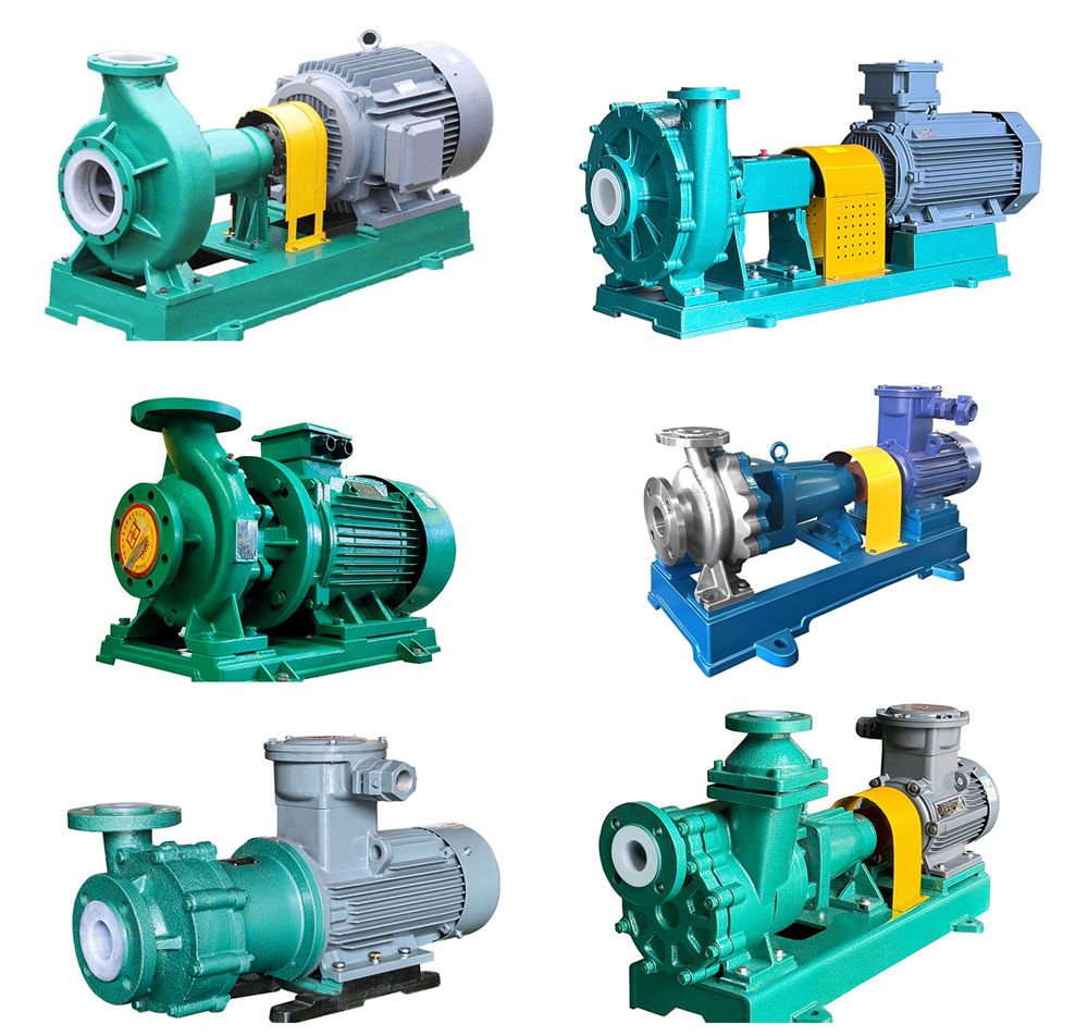
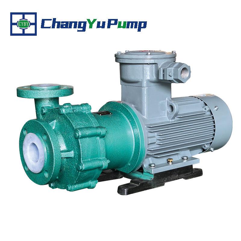
    Magnetic drive pumps (commonly referred to as magnetic pumps) are sealed pumps that transmit power through magnetic coupling. They are suitable for highly corrosive, flammable, volatile, or high-purity media. Their advantages include excellent sealing performance and safety and environmental friendliness. However, they also have limitations such as efficiency constrained by magnetic coupling and susceptibility to wear in the isolation sleeve. If you wish to gain a deeper understanding of magnetic drive pumps—including their operating principles, detailed structure, application scenarios, performance advantages, common issues, and maintenance techniques—please continue reading below. Working Principle of Magnetic Drive Pump   Magnetic drive pumps operate based on the principle of magnetic coupling. When the motor drives the outer magnetic rotor to rotate, the magnetic field generated by the outer rotor is transmitted through an air gap to the inner magnetic rotor. The inner rotor is connected to the impeller, which rotates under magnetic force, driving the impeller to convey liquid. Since there is no physical contact between the outer and inner magnetic rotors, magnetic force transmission replaces traditional mechanical seals, eliminating leakage issues caused by seal wear. This design makes magnetic drive pumps particularly suitable for applications requiring liquid leak prevention, transporting highly corrosive, flammable, volatile, or high-purity media. The absence of mechanical contact throughout the process reduces wear, effectively enhancing system stability and safety.   The Following Is Its Operational Sequence: 1. Motor Start-up: Upon energization, the motor commences operation, driving the outer magnetic rotor to rotate. 2. Magnetic Coupling Transmission: The outer magnetic rotor generates a rotating magnetic field, which is transmitted to the inner magnetic rotor through the isolation sleeve. 3. Impeller Drive: The inner magnetic rotor is tightly connected to the impeller. Under magnetic force, they rotate synchronously, propelling the liquid flow. 4. Liquid Intake and Discharge: The impeller's rotation generates centrifugal force, drawing in liquid at the inlet, accelerating it, and discharging it through the outlet, creating a stable fluid transfer process. 5. Sealing and Leak Prevention: The isolation sleeve separates the inner and outer magnetic rotors, eliminating mechanical shaft penetration and avoiding leakage risks associated with traditional mechanical seals. 6. Cooling and Lubrication: Some pump designs incorporate cooling circuits that utilize the conveyed medium to cool and lubricate bearings and the isolation sleeve, ensuring long-term stable operation. 
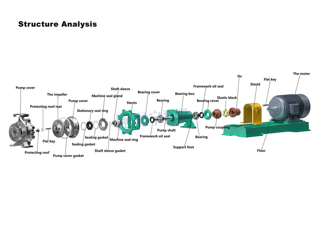
Magnetic Drive Pump Parts 1. Pump Housing: Protects internal components while supporting and securing all parts. 2. Impeller: Rotates and accelerates to convey liquid. 3. Outer Magnetic Rotor: Driven by the motor, generates a magnetic field and couples with the inner magnetic rotor to transmit power. 4. Inner Magnetic Rotor: Couples with the outer magnetic rotor, transmitting power through magnetic force generation. 5. Isolation Sleeve: Constructed from non-magnetic material, it isolates the inner and outer magnetic rotors to prevent fluid leakage. 
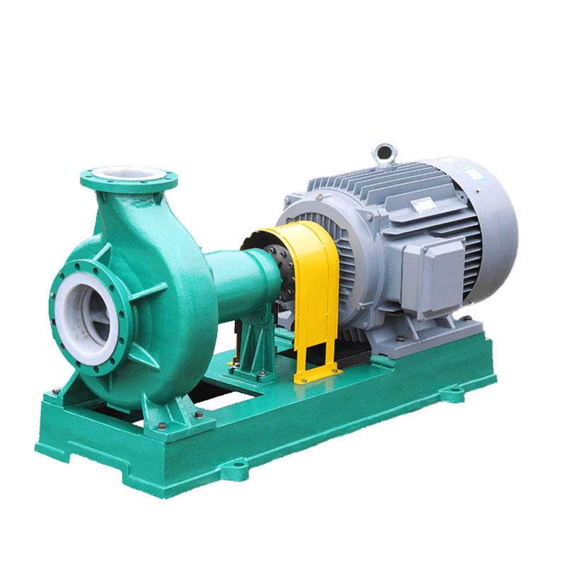
6. Electric Motor: Supplies power to the magnetic drive pump, driving the outer magnetic rotor's rotation to initiate pump operation. Magnetic Drive Pump Uses   Magnetic drive pumps are primarily used for conveying corrosive, flammable, volatile liquids, or those requiring high purity. Since they operate without mechanical seals, they effectively eliminate leakage. These pumps are widely employed in chemical processing, pharmaceutical manufacturing, food processing, environmental treatment, and the electronics industry, proving particularly suitable for transporting liquids with stringent safety and hygiene requirements. Advantages and Disadvantages of Magnetic Drive Pumps   Advantages: Magnetic drive pumps utilize magnetic coupling to eliminate mechanical seals, thereby avoiding the common seal leakage issues found in traditional centrifugal pumps. This significantly reduces leakage risks and makes them suitable for transporting corrosive, flammable, or high-purity liquids. Additionally, they operate smoothly, require minimal maintenance, offer high adaptability, and can substantially enhance system safety and reliability.   Disadvantages: Magnetic drive pump efficiency is constrained by magnetic coupling, and its performance in handling high-viscosity liquids is limited. Due to wear between the inner and outer magnetic rotors, the isolation sleeve requires periodic replacement, increasing maintenance costs. Furthermore, they are relatively expensive and typically suited for specialized applications with stringent safety requirements. Magnetic Drive Pump Maintenance   Maintenance of magnetic drive pumps primarily involves regular inspections of the magnetic drive system, isolation sleeve, lubrication, and cooling systems. To prevent fluid leakage and ensure proper pump operation, the isolation sleeve should be inspected and replaced periodically. Additionally, the magnetic drive system must be kept clean to prevent damage to the magnetic rotor. The lubrication system should maintain proper oil levels and cleanliness to avoid overheating or dry running, which can impair pump efficiency and lifespan. Regular system inspections and maintenance effectively enhance operational stability and extend equipment service life. Magnetic Drive Pump Issues   The primary problems with magnetic drive pumps include the following: First, magnetic coupling limits the pump's operational efficiency, making it unsuitable for conveying high-viscosity liquids. Second, friction between the inner and outer magnetic rotors causes wear on the isolation sleeve, necessitating regular inspection and replacement to prevent leakage risks. Finally, magnetic drive pumps carry a higher price tag. While offering robust sealing performance and safety, their maintenance costs and relatively high price point make them more suitable for specific applications with stringent safety requirements.   FAQS 1. What are the different types of magnetic drive pumps? 
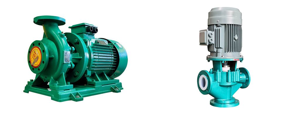
Magnetic drive pumps are primarily categorized into the following types based on application requirements and structural design: 1. External rotor magnetic drive pumps: The external rotor is directly connected to the motor, suitable for applications requiring medium to low flow rates and high pressure. 2. Internal rotor magnetic drive pumps: The internal magnetic rotor is directly connected to the impeller, suitable for applications requiring higher flow rates and greater head. Commonly used in chemical and pharmaceutical industries. 3. Side-flow magnetic drive pumps: The pump body structure allows liquid to flow along the side of the pump, typically used for conveying corrosive or high-viscosity liquids. 4. High-Temperature Resistant Magnetic Drive Pump: Constructed from heat-resistant materials, it operates stably at elevated temperatures and handles high-temperature media. 5. Corrosion-Resistant Magnetic Drive Pump: Manufactured from corrosion-resistant materials (e.g., stainless steel or fluoroplastics), it conveys highly corrosive liquids. These diverse magnetic drive pump types, differing in materials, structure, and operation, meet varied conveying demands across industries, delivering more efficient and safer solutions for industrial environments.What Is The Difference Between Magnetic Drive Pumps And Centrifugal Pumps?   
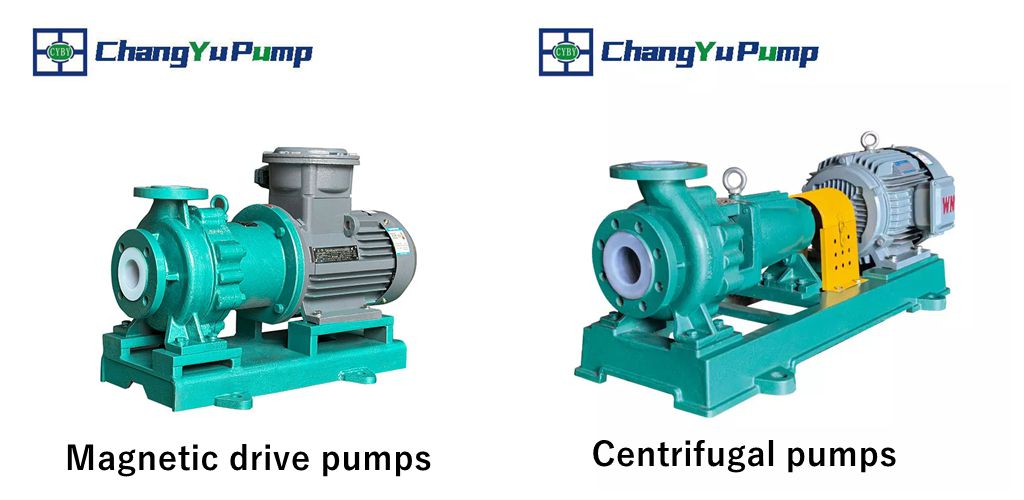
The primary distinction between magnetic drive pumps and centrifugal pumps lies in their drive mechanisms and seal designs. Magnetic drive pumps transmit power through magnetic coupling, eliminating the need for traditional mechanical seals. This design prevents leakage issues, making them ideal for conveying corrosive, flammable, or high-purity liquids. In contrast, centrifugal pumps use an electric motor to directly drive the impeller's rotation, relying on mechanical seals to prevent liquid leakage. This approach carries inherent leakage risks, particularly when handling specialized media. Magnetic drive pumps operate more smoothly and require simpler maintenance, making them ideal for applications demanding high sealing integrity. Centrifugal pumps, meanwhile, are widely used for conveying ordinary liquids with high flow rates and low pressure requirements. What Are The Advantages Of Magnetic Drive Pumps?   The primary advantage of magnetic drive pumps lies in their leak-free design. Unlike traditional pumps that rely on mechanical seals and may pose leakage risks, they are particularly suitable for transferring corrosive, flammable, or high-purity liquids. They transmit power through magnetic coupling, reducing wear and maintenance requirements while enabling long-term stable operation. This effectively enhances system safety and reliability. The absence of mechanical seals also grants magnetic drive pumps superior corrosion resistance and extended service life. Consequently, selecting this technology enables more environmentally friendly, secure, and efficient liquid transfer operations.The above provides a comprehensive explanation of how magnetic drive centrifugal pumps operate. If you require the transfer of liquids with stringent sealing requirements and prioritize operational safety during production, magnetic drive pumps represent an excellent choice. For any technical inquiries or selection assistance, please contact our team. We will provide customized solutions tailored to your needs. We look forward to hearing from you!      
    Read More
  • How Does a Centrifugal Pump Operate: Safety Operation Guide How Does a Centrifugal Pump Operate: Safety Operation Guide
    Aug 30, 2025
    Centrifugal pumps are among the most common fluid transfer devices in industrial production. They operate by generating centrifugal force through impeller rotation, accelerating fluid and conveying it to the target location. Due to their simple structure, stable flow rate, and easy maintenance, they are widely used in chemical, water treatment, energy, pharmaceutical, and other industries. However, improper operation not only shortens equipment lifespan but may also cause safety incidents. Therefore, mastering standardized operating procedures is crucial for ensuring stable production while safeguarding personnel and equipment. The following systematically outlines key operational points for starting, running, and stopping centrifugal pumps to help achieve safe and efficient operation. I. Pre-Operation Preparations Before starting the centrifugal pump, conduct a systematic inspection to ensure the equipment is in a safe condition:   Document and Record Review: Verify maintenance records are complete and data accurate. Prepare operational log forms. Environmental Cleanup: Clear debris from the pump body and surrounding area to ensure a tidy operating zone. Structural Integrity Check: Verify foundation bolts are tightened, motor grounding is secure, and inlet piping, auxiliary components, and instruments are intact. Coupling and Rotation Direction Verification: Inspect coupling connection status. Before coupling, confirm motor rotation direction aligns with the pump body's directional arrow. Lubrication System Inspection: Ensure adequate lubricant level in the sump (oil level approximately 2mm below the centerline of the dipstick), with qualified oil quality and level within the 1/2 to 2/3 range. Cooling and Sealing System: Verify cooling water flow is unobstructed and seal oil pressure exceeds pump inlet pressure by 0.05–0.15MPa. Hand Turning Test: Manual rotation should exhibit no binding or abnormal noise. Temperature Preconditioning: Preheat high-temperature pumps; pre-cool low-temperature pumps. Priming and Venting: For suction-side operation, prime the pump or evacuate air; for back-priming operation, fill with liquid and vent air, then close the discharge valve. Electrical Inspection: Contact an electrician to perform motor insulation testing before energizing. II. Startup Procedure Close the discharge valve during centrifugal pump startup to reduce startup load and protect the motor:   Close inlet/outlet pressure gauge valves, outlet valve, and bypass pipe valve. Start the motor (may jog first to confirm correct rotation). Gradually open the outlet valve while simultaneously monitoring current and pressure values to ensure they do not exceed rated limits. Check for leakage from mechanical seals or packing seals; mechanical seal leakage should be less than 10 drops per minute (for light oil). Verify normal operation of the cooling and lubrication systems.   III. Operational Monitoring and Maintenance During normal pump operation, continuously monitor the following:   Bearing and motor temperatures: Bearing temperature rise must not exceed 75°C. Forced lubrication system oil temperature should remain below 28°C. Flow regulation: Never adjust flow using the inlet valve to prevent cavitation. Install a bypass pipe for prolonged low-flow operation. Abnormal noise monitoring: Immediately investigate or shut down upon detecting unusual sounds. Vibration and Seal Condition: Regularly record vibration readings and verify seal leakage remains within permissible limits. Periodic Lubricant Replacement: Lubricant replacement is recommended every 1500 operating hours.   IV. Shutdown Procedure Proper shutdown prevents water hammer, freezing, and equipment damage. Follow these steps:   Slowly close the discharge valve (close the suction valve in backflow conditions). Disconnect the motor power supply. Close valves in the external priming seal system. In low-temperature environments, drain all liquid from the pump to prevent freezing. For long-term shutdown, clean the pump, apply rust prevention, seal the inlet and outlet ports, and conduct regular inspections and maintenance.   In summary Proper operation and maintenance of centrifugal pumps are crucial for ensuring long-term stable performance and extending service life. Every step—from comprehensive pre-startup inspections to continuous monitoring during operation and standardized shutdown procedures—is vital. Adhering to the above steps not only enhances production efficiency but also minimizes the risk of malfunctions and safety incidents.   Should you encounter any operational issues or require further technical support, please contact our professional technical team at any time. We will provide timely and reliable solutions.
    Read More
  • What is a Magnetic Drive Pump What is a Magnetic Drive Pump
    Sep 22, 2025
    Magnetic drive pumps (MDP) are primarily used for transporting corrosive chemicals. Unlike conventional centrifugal pumps (which often leak due to mechanical seal failure), magnetic pumps rely on magnetic force to drive fluid flow. They require no seals, eliminate leakage, and demand minimal maintenance. This article provides a detailed overview of magnetic drive pumps, including their operating principles, core components, and maintenance considerations. Please continue reading.   What is a Magnetic Drive Pump? A Magnetic Drive Pump (MDP) is a classic example of a seal-less pump. In traditional centrifugal pumps, the connection between the motor and pump body relies on rubber or carbon seals to prevent leakage. However, these seals wear out very quickly in high-frequency industrial operating environments, typically requiring replacement within less than three months. Magnetic drive pumps replace traditional sealing structures with magnetic coupling transmission devices, enabling non-contact connection between the motor and impeller. This effectively eliminates leakage risks, significantly enhancing pump reliability and service life. How Does a Magnetic Pump Work? Magnetic drive pumps operate by using an electric motor to rotate an outer magnetic rotor. The magnetic field penetrates an isolation sleeve, driving the inner magnetic rotor and impeller to rotate synchronously, achieving non-contact power transmission. This design replaces the traditional dynamic seal prone to leakage with a static seal, enabling zero-leakage operation. Most magnetic pumps employ synchronous magnetic drive, where inner and outer magnets rotate in unison via magnetic force. In asynchronous magnetic drive (torque ring type), the inner magnet is replaced by a torque ring that rotates at a slightly lower speed under the external magnetic field, enabling operation under higher temperature conditions. The working principle involves the following steps:   (1) Permanent magnets generate a magnetic field that attracts and fixes the impeller in position through magnetic force; (2) The motor drives the pump shaft to rotate, thereby turning the impeller; (3) The impeller's rotation creates negative pressure inside the pump casing, drawing in liquid; (4) The liquid is expelled by the impeller's centrifugal force, completing the pumping process.   Parts Magnetic drive pumps primarily consist of the following components: Pump Housing: Supports and conveys liquids while creating the required pressure environment; Impeller: Pressurizes and conveys liquids during rotation; Motor: Serves as the power source, driving the external magnetic rotor; Permanent Magnets: Generate a stable magnetic field, transmitting power via magnetic coupling to achieve non-contact drive.   Magnetic Drive Pump Applications Chemical Industry: Suitable for conveying highly corrosive media such as sulfuric acid, hydrochloric acid, and sodium hydroxide, ensuring zero leakage and extended equipment lifespan. Pharmaceutical Industry: Enables precise and stable liquid transfer in drug manufacturing, particularly suited for high-purity and contamination-free requirements. Petroleum Industry: Used for conveying and circulating crude oil, petrochemical solvents, and drilling fluids, reducing leakage risks and equipment wear. Environmental Protection: Widely applied in treating and transporting sewage, waste liquids, and hazardous chemical effluents, offering safety and reliability. Electroplating & Semiconductor: Suitable for conveying highly corrosive special chemical media like electroplating solutions and etching solutions, ensuring stable production line operation.   Magnetic Drive Pump Advantages and Disadvantages Magnetic drive pumps offer key advantages including leak-free operation, low maintenance, and high reliability. They are particularly suited for conveying corrosive, toxic, or volatile liquids, finding extensive use in demanding industries such as chemical processing, pharmaceuticals, and environmental protection. However, they also have limitations, such as slightly lower efficiency, sensitivity to media and temperature, high requirements for installation precision and isolation sleeve material. Additional auxiliary measures and cost investments are needed when conveying media containing solid particles or high-temperature media. Below are the advantages and disadvantages of magnetic drive pumps: Magnetic Drive Pump Advantages   Leak-Free Design: Utilizes magnetic coupling transmission, eliminating mechanical shaft seals and completely removing the risk of liquid leakage. Overload Protection: Inherent overload protection ensures safer and more reliable operation. Low Maintenance: Simplified structure minimizes seal replacement frequency and reduces maintenance workload. Wide Applicability: Moderate manufacturing complexity (excluding stringent magnetic circuit and material requirements) makes it suitable for large-scale industrial applications.   Magnetic Drive Pump Disadvantages Efficiency Limitation: Slightly lower efficiency than conventional centrifugal pumps; prohibited from dry running or operating below 30% of rated flow. Medium Restriction: Unsuitable for media containing solid particles or magnetic impurities to prevent wear and blockage. Temperature Sensitivity: Limited by permanent magnet and isolation sleeve materials; prolonged high temperatures may cause demagnetization or damage. Complex Requirements: Demands high installation precision, cooling systems, and specialized isolation sleeve materials, increasing cost and technical complexity. What Is a Magnetic Drive Pump Vs Centrifugal Pump The primary distinction between magnetic drive pumps and conventional centrifugal pumps lies in their sealing mechanisms. Magnetic drive pumps utilize magnetic coupling for leak-free transmission, whereas centrifugal pumps rely on mechanical seals or packing seals, which carry inherent leakage risks. Comparison Items Magnetic Drive Pump Traditional Centrifugal Pump Sealing Method Static seal + magnetic coupling, leak-free Dynamic mechanical seal or packing seal, prone to wear and leakage Maintenance Cost Low pressure, no seal replacement required High leakage rate, requiring regular seal replacement Applicable Media Highly corrosive, toxic, hazardous, and volatile liquids Suitable for ordinary water, mildly corrosive or non-hazardous media Operational Safety High pressure, to avoid leakage and environmental risks Relatively low reliability, potential safety hazards due to leakage Structural Complexity Slightly higher pressure, requires isolation sleeve and magnetic coupling device Simple design with direct shaft drive Applicable Operating Conditions High pressure, suitable for high-demand industries such as chemicals, pharmaceuticals, environmental protection, and semiconductors Common applications include industrial water supply, circulation, and drainage systems Summary In summary, magnetic drive pumps are a leak-free pump type that utilizes magnetic coupling transmission to achieve power output. With their safety, reliability, and low maintenance characteristics, they are widely used in industries with extremely high requirements for medium transportation, such as chemical, pharmaceutical, environmental protection, and petroleum. Although they have certain limitations in efficiency, temperature adaptability, and fluid restrictions, magnetic drive pumps remain an ideal choice for handling corrosive, toxic, or high-value fluids when properly selected and applied.   Should you have any questions regarding magnetic drive pump selection, application, or technical specifications, please feel free to contact our professional team at any time. We will provide you with one-on-one solutions and technical support.          
    Read More
1 2 3 4 5 6 7

Leave a message

Leave a message
If you are interested in our products and want to know more details,please leave a message here,we will reply you as soon as we can.
Submit

Our hours

Mon 11/21 - Wed 11/23: 9 AM - 8 PM
Thu 11/24: closed - Happy Thanksgiving!
Fri 11/25: 8 AM - 10 PM
Sat 11/26 - Sun 11/27: 10 AM - 9 PM
(all hours are Eastern Time)

Contact Us:jade@changyupump.com

Home

Products

whatsApp

contact